
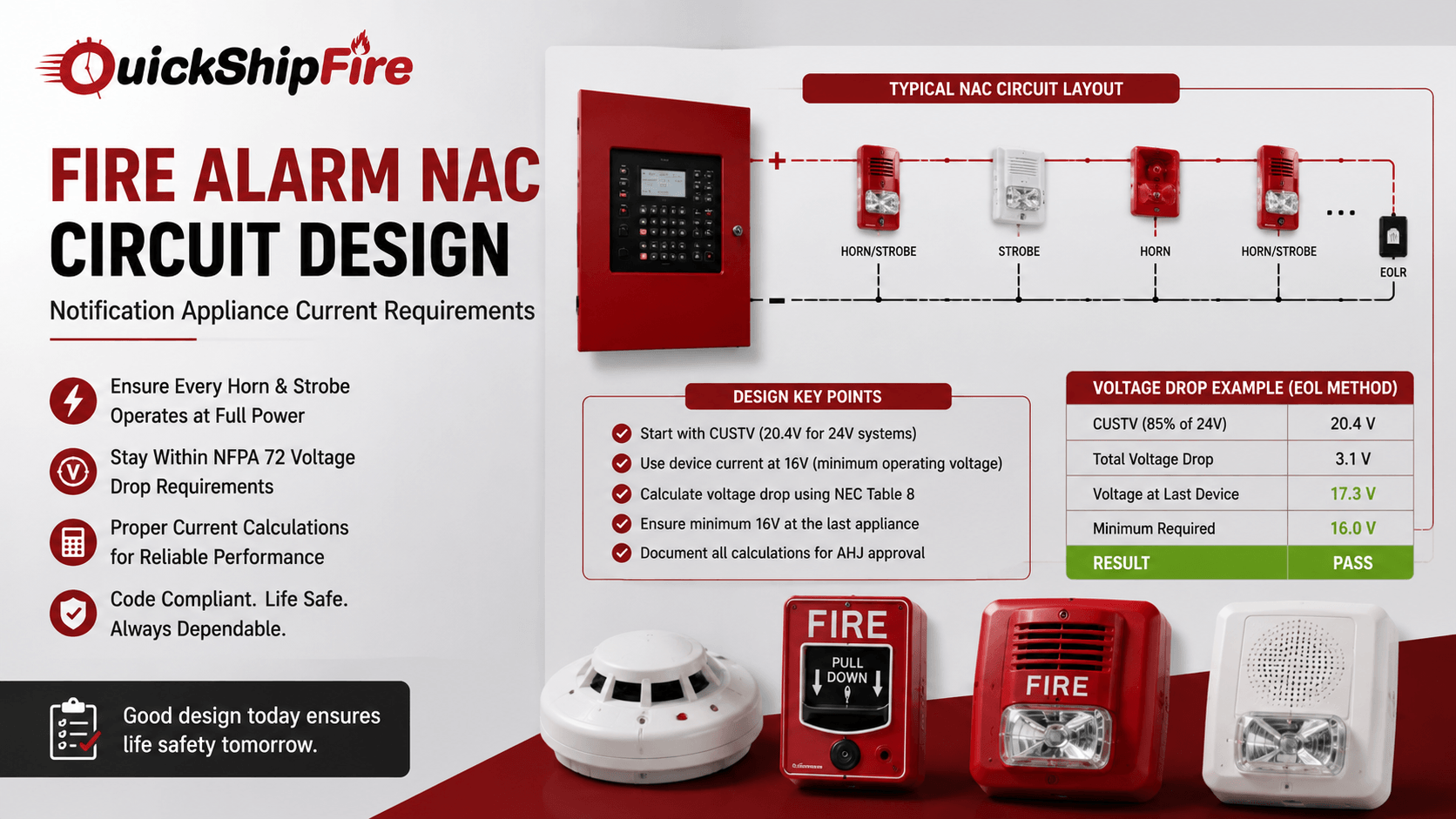
A fire alarm system can detect a fire perfectly and still fail the people inside the building if the horns and strobes at the far end of a circuit never reach full volume or brightness. That is the practical reality behind fire alarm NAC circuit design: notification appliance circuits carry real current over real wire, and voltage drops as it travels, which means every device on the circuit has to be verified to operate at the actual voltage it will see, not the nominal voltage at the panel. This guide covers how NAC circuits are calculated, what NFPA 72 requires, and the design decisions that keep every horn and strobe on a fire alarm NAC circuit working the way it is supposed to.
What Is a Fire Alarm NAC Circuit?
Every fire alarm NAC on a system exists for one purpose: getting occupants to react and move toward an exit. Getting the underlying circuit design right is what makes that notification dependable rather than a gamble on wire length and device count.
A Notification Appliance Circuit, or NAC, is a supervised, polarity-reversing power circuit that drives horns, strobes, horn/strobes, and other audible or visible notification appliances from the panel. Any fire alarm NAC that does not have a notification appliance connected to it is technically classified as a control circuit rather than a NAC, but the design math is the same either way. Troubles on a NAC, including opens, shorts, or ground faults, must be reported at the panel within 200 seconds under NFPA 72, and the circuit is supervised continuously so a wiring fault is caught long before an actual alarm condition would need the circuit to perform.
Every fire alarm NAC circuit is defined by two variables that drive its design: the total current draw of every notification appliance on the circuit, and the voltage drop across the wire run to the most distant device. Get either one wrong and the last strobe on the circuit may fail to flash at its rated candela, or the last horn may fail to sound at its rated decibel level, even though the panel itself is functioning normally.
NFPA 72 Voltage Drop Requirements for a Fire Alarm NAC
NFPA 72 requires that every notification appliance on a fire alarm NAC receive enough voltage to operate correctly under worst-case conditions, which means the calculation has to start from the Control Unit Start Terminal Voltage, or CUSTV, rather than the panel’s full nominal voltage. For a standard 24-volt system, code requires the control unit to be evaluated at 85 percent of nameplate voltage, which works out to a CUSTV of 20.4 volts. Because most 24-volt notification appliances are rated to operate down to a minimum of 16 volts, the maximum allowable voltage drop across a fire alarm NAC circuit is typically 4.4 volts, not the roughly 20 percent margin many people assume from general electrical wiring rules.
The 20.4-volt starting point exists because UL 864 requires the system to keep operating as its batteries discharge toward the end of their standby period, not just when the batteries are freshly charged. Designing a fire alarm NAC circuit around a full 24 volts at the panel, rather than the reduced worst-case voltage, is one of the most common mistakes that leads to failed inspections and underperforming notification appliances in the field.
- Start with the Control Unit Start Terminal Voltage (20.4V for most 24V systems), not the nominal 24V rating.
- Use each appliance’s rated current draw at its lowest operating voltage, typically 16V, not at 24V.
- Calculate total wire resistance using NEC Chapter 9, Table 8 conductor properties for the specified wire gauge.
- Confirm the voltage at the last device on the circuit stays above the appliance’s minimum operating voltage, typically 16V.
- Document every fire alarm NAC voltage drop result for AHJ submittal, since it is a required part of the design package.
How to Calculate Voltage Drop on a Fire Alarm NAC Circuit
There are two accepted methods for calculating voltage drop on a notification appliance circuit: End of Line (EOL) and Point to Point (PTP). Both are permitted under NFPA 72, but they trade accuracy for simplicity in opposite directions.
End of Line (EOL) Method
The EOL method is the simpler of the two and is often done by hand. Add up the total current draw of every device on the fire alarm NAC circuit at minimum operating voltage, then add up the total wire length of the run, doubling it for a Class B circuit since current travels out and back on two conductors. Multiply the total wire length by the resistance-per-foot value for the specified wire gauge, taken from NEC Chapter 9, Table 8, to get total circuit resistance. Multiply that resistance by the total current draw to get the voltage drop, then subtract that figure from the CUSTV to confirm the voltage remaining at the last device. Because EOL assumes every device draws current all the way to the far end of the circuit, it is conservative and leaves margin for future device additions, but it can overstate the actual drop on circuits with devices spread out along the run rather than clustered at the end.
Point to Point (PTP) Method
The Point to Point method calculates voltage drop segment by segment, accounting for the actual current load and wire resistance between each device rather than assuming full current for the entire run. This requires more calculation steps, and most designers use dedicated NAC circuit design software rather than working it by hand on any circuit with more than a handful of devices, but the result is a more accurate picture of the true voltage available at each appliance. PTP calculations are especially useful when a circuit is close to failing the EOL method, since they frequently reveal enough real margin to avoid splitting the circuit or upsizing the wire.
- EOL (End of Line) is faster to calculate by hand and produces a conservative, worst-case result.
- PTP (Point to Point) accounts for actual device placement along the circuit and is more accurate on complex layouts.
- If a fire alarm NAC circuit fails its voltage drop check, splitting devices across two circuits is often the simplest fix.
- Upsizing wire gauge reduces resistance and voltage drop but adds material and labor cost to the installation.
- Software-based point to point tools are standard practice on any circuit with more than a few devices.
EOL vs PTP: Which Fire Alarm NAC Calculation Method to Use
| Factor | End of Line (EOL) | Point to Point (PTP) |
| Calculation effort | Low; can be done by hand with a calculator | High; typically requires design software |
| Accuracy | Conservative; may overstate voltage drop | Accurate; reflects actual device placement |
| Best for | Simple circuits, quick estimates, early design | Complex circuits, marginal calculations, final submittals |
| Assumes | All current flows to the farthest point on the circuit | Current diminishes as devices are reached along the run |
| Typical result | More conservative headroom, may require oversizing | Tighter, more realistic design with less unnecessary cost |
Class A vs Class B Fire Alarm NAC Wiring
Fire alarm circuits, including the NAC, are wired in one of several classes defined by NFPA 72, with Class A and Class B being the most common configurations for a fire alarm NAC. A Class B NAC circuit is a single loop that terminates at an end-of-line resistor; if the wire is cut, everything downstream of the break loses power and supervision. A Class A circuit routes a second, redundant conductor back to the panel, so a single break does not take the downstream devices offline; the panel simply reports the fault while notification continues to function on both legs of the loop. Class A wiring costs more in material and labor because it requires a full second run back to the panel, but many occupancies, particularly high-rises and larger assembly buildings, require it for survivability.
The wiring class chosen for a fire alarm NAC circuit also affects total voltage drop, since a Class A circuit effectively doubles the conductor length that must be accounted for in the resistance calculation, even though it is not doubled the same way a Class B loop-and-return is for current draw. Confirming which class the local code and the authority having jurisdiction require early in design prevents a costly rework of the entire notification circuit later.
Equipment That Affects Fire Alarm NAC Performance
Reliable NAC circuit performance depends on more than the math. The devices themselves, the panel driving them, and the power behind the whole system all have to be matched correctly. System Sensor notification appliances and similar horn/strobe products publish current draw at multiple voltage and candela settings, and using the correct figure for the selected candela setting, rather than a generic average, is essential to an accurate calculation. A fire alarm power supply sized with adequate reserve capacity ensures the panel itself can deliver the rated output voltage under full alarm load, since a marginal power supply will undermine even a perfectly calculated NAC circuit.
On an addressable fire alarm system, a properly configured signaling line circuit module handles initiating devices separately from notification, which keeps NAC circuit design isolated from detector wiring decisions. This separation matters when planning a retrofit or expansion, particularly one that also involves extending pull station wiring to a new area of the building, since new notification appliances added to an existing circuit change the current draw and voltage drop for every device already on that circuit.
- Use manufacturer current-draw data at the specific candela and voltage setting selected, not a generic average figure.
- Size the fire alarm power supply with margin above the calculated worst-case alarm current draw.
- Keep NAC wiring separate from initiating device and signaling line circuit wiring.
- Recalculate voltage drop any time a device is added to or removed from an existing fire alarm NAC circuit.
- Verify wire gauge and conductor count match what was assumed in the original design.
Common Fire Alarm NAC Design Mistakes
Even experienced designers run into a handful of recurring problems on a fire alarm NAC. Calculating voltage drop from a full 24 volts instead of the correct 20.4-volt CUSTV baseline overstates the available margin and is one of the most common causes of a circuit that passes on paper but fails in the field. Mixing horn/strobes from different manufacturers on the same circuit without confirming compatible current draw and synchronization protocols can create sync conflicts even when the voltage math checks out. And treating a voltage drop calculation as a one-time exercise, rather than repeating it whenever the circuit is modified, is how previously compliant systems drift out of compliance over the life of a building.
A field-verified voltage drop calculation at commissioning, confirming actual measured voltage at the last device rather than relying solely on the paper calculation, catches installation errors such as incorrect wire gauge or an unplanned splice that a design calculation alone cannot reveal.
Whether you are designing a new fire alarm NAC circuit or troubleshooting an existing one, having the right notification appliances, power supplies, and panel components on hand makes the difference between a quick fix and a delayed inspection. QuickShipFire stocks notification appliances, power supplies, and fire alarm control panel components from System Sensor, Wheelock, Notifier, Fire-Lite, and other leading manufacturers, including hard-to-find parts for systems being expanded or serviced. Request a quote and our team will help you get the right components shipped fast.
Conclusion
Designing a fire alarm NAC circuit correctly comes down to respecting two numbers: the true worst-case starting voltage at the panel, and the actual current draw of every notification appliance on the circuit at that voltage. Whether the calculation is done using the simpler End of Line method or the more precise Point to Point method, the goal is the same, confirming that the last horn or strobe on the circuit still receives enough voltage to perform exactly as it is rated to. Combined with the correct wiring class, an appropriately sized control panel and power supply, and a field-verified measurement at commissioning, a properly designed fire alarm NAC circuit keeps notification reliable for the life of the building.
Frequently Asked Questions
What does NAC stand for in a fire alarm system?
NAC stands for Notification Appliance Circuit, the supervised circuit that powers horns, strobes, and horn/strobe combination devices from the control panel.
What is the maximum voltage drop allowed on a fire alarm NAC circuit?
It depends on the notification appliance, but for a typical 24-volt system with devices rated to operate down to 16 volts, the maximum allowable drop from the 20.4-volt Control Unit Start Terminal Voltage is 4.4 volts.
Why use 20.4 volts instead of 24 volts on a fire alarm NAC?
UL 864 requires the system to keep working as its standby batteries discharge, not only when freshly charged. NFPA 72 calculations therefore start from 85 percent of nameplate voltage, which is 20.4 volts on a 24-volt system, to reflect true worst-case operating conditions.
What is the difference between the EOL and PTP methods for calculating fire alarm NAC voltage drop?
The End of Line method assumes all current flows to the farthest point on the circuit and is simpler but more conservative. The Point to Point method calculates voltage drop segment by segment based on actual device placement, producing a more accurate result, usually with the help of design software.
What happens if a fire alarm NAC circuit fails its voltage drop check?
The most common fixes are splitting the devices across two separate NAC circuits to reduce the load and drop on each one, or upsizing the wire gauge to reduce resistance. Both approaches reduce the total voltage drop to bring the last device back within its rated operating range.
What is the difference between Class A and Class B NAC wiring?
A Class B circuit is a single loop terminating at an end-of-line resistor; a wire break disables everything downstream. A Class A circuit runs a second, redundant conductor back to the panel, so a single break does not disable notification, though it does increase material and labor cost.
Can different manufacturers’ notification appliances be mixed on the same fire alarm NAC circuit?
It depends on the devices and their synchronization protocol. Mixing horn/strobes from different manufacturers without confirming compatible current draw and sync compatibility can create conflicts even when the underlying voltage math is correct, so compatibility should always be verified before mixing product lines on one circuit.