Of all the technical decisions that shape a fire alarm system’s long-term reliability, few carry more weight than circuit wiring class. Understanding fire alarm Class A vs Class B wiring is not just a code compliance exercise it directly determines how your system behaves when wiring faults occur, which in a real fire emergency can be the difference between a fully functional system and one that has gone silent in exactly the area that needs it most.
NFPA 72 defines the circuit class requirements that govern every fire alarm installation in the United States from the smallest Class B zone circuit in a single-story office to the fully redundant Class A and Class X topologies required in hospitals, high-rises, and mission-critical facilities. Yet in practice, many contractors and facility managers have only a surface-level understanding of what these classes actually mean for system behavior under fault conditions.
This guide cuts through the terminology and gives you a working, practical understanding of Class A, Class B, and Class X fire alarm circuits: how each is wired, how each responds to opens and shorts, where NFPA 72 requires each class, and what the real-world implications are for system design, maintenance, and upgrades.
Why Circuit Class Is a Safety-Critical Design Decision
Every fire alarm circuit whether it’s an Initiating Device Circuit (IDC) carrying smoke detector signals, a Signaling Line Circuit (SLC) communicating with addressable devices, or a Notification Appliance Circuit (NAC) driving horns and strobes is subject to real-world wiring faults. Wires get pinched during construction. Insulation degrades. Rodents chew through cables. Mechanical damage occurs in occupied buildings every day.
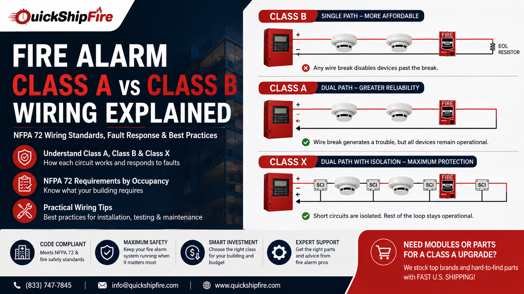
The circuit class defines what happens to your fire alarm system when a fault occurs. On a Class B circuit, a single wire break can disable every device past that break silently, with no alarm capability in that section of the building. On a Class A circuit, that same wire break generates a trouble condition but leaves every device operational through the circuit’s redundant return path. On a Class X circuit, even a complete short circuit is isolated, and the rest of the loop continues to function.
This is why circuit class selection is a fundamental fire alarm system design decision not an afterthought and why NFPA 72 mandates Class A wiring for higher-risk occupancies where system failure during a fire event could directly cost lives.
NFPA 72 Circuit Classifications: The Regulatory Foundation
NFPA 72 – the National Fire Alarm and Signaling Code provides the framework that defines all fire alarm circuit supervision requirements in the United States. Understanding a bit of its history helps explain the terminology you’ll encounter on existing systems and in older documentation.
| Styles vs Classes – A Brief History of NFPA 72 Circuit Terminology |
| Before 2010 – “Wiring Styles”: NFPA 72 defined circuits by “style” – Style 4, Style 6, Style 7, Style B, Style Y, Style Z – each with specific fault-response requirements. These styles described how the circuit behaved under open and short circuit conditions. |
| 2010 Edition and Later – “Circuit Classes”: NFPA 72 replaced the Style framework with a simplified three-class system: Class A, Class B, and Class X. The Classes describe fault tolerance more intuitively, though the underlying wiring requirements remain functionally equivalent to their Style predecessors. |
| Why This Matters Today: Many existing systems were designed and documented using Style terminology. A system with “Style 6 IDC” wiring is equivalent to Class A. “Style 4” equals Class B. Technicians working on legacy systems need to understand both frameworks – the NFPA 72 circuit styles correspond directly to the current class designations. |
The current NFPA 72 circuit styles framework applies across three circuit types that you’ll encounter in virtually every fire alarm installation: The Initiating Device Circuit (IDC) that carries alarm signals from detectors and pull stations, the Signaling Line Circuit (SLC) that communicates with addressable devices on a two-wire loop, and the Notification Appliance Circuit (NAC) that powers and supervises horn and strobe devices. Class designations apply to all three.
Class B Fire Alarm Circuits: How They Work and Where They Apply
A Class B fire alarm circuit uses a single-path topology. Wire leaves the panel, passes through each device in series, and terminates at an end-of-line (EOL) device – typically a resistor installed at the last device on the circuit. The panel continuously monitors the current flowing through this path to verify circuit integrity.
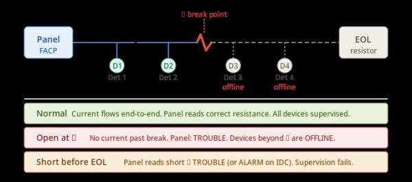
The critical operational consequence: on a Class B circuit, any single wire break between two devices disables every device between that break and the EOL device. Those devices cannot report an alarm, and the system cannot supervise them. The panel generates a trouble condition, but in the section of the building where the break occurred, fire detection capability may be entirely lost.
Despite this limitation, Class B circuits are widely and legitimately used because they are:
- Lower cost to install: Single-path wiring requires less cable and fewer conduit runs than a Class A return path.
- Simpler to troubleshoot: With a single wire path, open circuit faults are generally easier to locate using standard wiring resistance methods.
- Appropriate for many occupancies: NFPA 72 permits Class B in a wide range of commercial applications where the risk profile doesn’t demand the redundancy of Class A.
For the fire alarm initiating device circuit in small to mid-size commercial buildings, offices, retail stores, and non-critical industrial applications, Class B is often the correct and code-compliant choice — provided the AHJ and occupancy type do not require Class A.
Class A Fire Alarm Circuits: Redundancy That Keeps Your System Running
A Class A fire alarm circuit uses a dual-path topology. The circuit wire leaves the panel, passes through devices just like Class B, continues to the last device – but then returns to the panel on a separate pair of conductors entering through a different terminal. There is no end-of-line resistor; the panel itself terminates the loop at both ends and monitors both paths continuously.
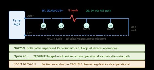
The defining advantage: on a Class A circuit, a single open-circuit fault does not take any device offline. Every detector, pull station, or module on the loop can still communicate with the panel because each device has two paths to reach it one through each direction around the loop. The panel flags the wire break as a trouble condition, alerting maintenance, but the system maintains full detection capability while repairs are made.
This fault tolerance is exactly why NFPA 72 Class A wiring requirements are mandated for high-risk occupancies. In a hospital where a wire break at 2 AM could silently disable an entire wing of smoke detectors, Class A is not optional it’s the only acceptable design. The same logic applies to high-rise buildings, large assembly occupancies, and facilities classified as having emergency systems.
The trade-off is installation cost: Class A requires roughly twice the wire of Class B for the same circuit, plus the additional conduit space for return conductors. Labor time increases accordingly. For facilities where the redundancy is code-required or genuinely necessary for life safety, this cost is a straightforward investment not a debate.
Class A vs Class B Fire Alarm Wiring: Direct Comparison
| Feature | Class A | Class B |
| Wire path topology | Dual path – out and return | Single path – out to EOL device |
| End-of-line resistor | Not required – panel terminates both ends | Required at last device on circuit |
| Open circuit fault response | All devices remain operational – TROUBLE only | Devices past break go OFFLINE – TROUBLE |
| Short circuit response | Section near short may drop – rest stays up | Circuit goes to TROUBLE or ALARM |
| NFPA 72 legacy style | Style 6 (IDC) / Style Z (SLC/NAC) | Style 4 (IDC) / Style Y (SLC) / Style B (NAC) |
| Installation cost | Higher – 2× cable + return conduit | Lower – single wire path |
| Fault tolerance | High – one break = zero device loss | Low – one break = devices offline |
| Common occupancies | Hospitals, high-rises, schools, data centers | Offices, retail, small commercial |
| AHJ requirement frequency | Required for high-risk occupancies | Permitted for most standard occupancies |
Class X Fire Alarm Circuits: Maximum Fault Tolerance
Class X is the highest fault-tolerance circuit classification in NFPA 72, introduced in the 2010 edition to address the one scenario that Class A cannot handle: a short circuit fault that takes down an entire section of the loop. While Class A survives an open-circuit break with full device operability, a short circuit anywhere on a Class A loop causes that section of the circuit to go into trouble and devices between the panel and the short may lose supervision.
Class X circuits solve this with fault isolation. Short-circuit isolation modules (SCIs) are installed at each device or at defined intervals along the loop. When a short circuit occurs, the isolation modules on either side of the fault detect the condition and disconnect that specific segment from the rest of the loop. All devices outside the isolated section continue to operate normally through the dual-path return route.
The Class X fire alarm circuit is required by NFPA 72 in specific high-risk scenarios, most commonly in emergency voice/alarm communication systems (EVACS) and in applications where even a momentary short-circuit fault could compromise life safety. It is also frequently specified by local AHJ amendments for hospitals, data centers, and mission-critical government facilities.
From an installation standpoint, Class X requires both the dual-path wiring of Class A and the addition of isolation modules throughout the circuit increasing both material and labor costs significantly compared to Class A or Class B. However, for occupancies where it is required, there is no alternative that meets the code requirement.
SLC Class A Wiring for Addressable Fire Alarm Systems
In modern addressable fire alarm systems, the Signaling Line Circuit (SLC) carries both power and communication signals to addressable devices. Applying Class A wiring to the SLC loop provides the same fault tolerance advantages as Class A IDC wiring but on the communication backbone that connects all addressable devices to the panel.
On an SLC Class A configuration, the two-wire loop leaves the panel on one set of terminals and returns on another set after completing the full device loop. If a wire break occurs anywhere along the SLC, devices on both sides of the break continue communicating with the panel through their respective path direction — maintaining full addressable device operation while the fault is located and repaired.
For Class X SLC configurations, short-circuit isolator modules are installed at each addressable device or at defined intervals along the SLC loop. These modules automatically detect and isolate a short-circuit fault on the loop, disconnecting only the faulted segment while all other devices continue operating normally. Isolator modules are a standard feature in many modern addressable detectors and are available as standalone modules for legacy devices that don’t include built-in isolation.
| SLC Wiring Classes at a Glance – Class B, A, and X |
| SLC Class B (Style 4): Single-path SLC loop. EOL device at last addressable point. Any wire break disables all devices past the break and generates a trouble condition at the panel. |
| SLC Class A (Style 6): Dual-path SLC loop – return conductors connect back to panel on separate terminals. Wire break generates trouble but all devices on both sides remain operational. Most common Class A SLC configuration in commercial systems. |
| SLC Class X (Style 7): Dual-path SLC with short-circuit isolation modules at each device or device group. Both open-circuit and short-circuit faults are isolated. Maximum fault tolerance – required for EVAC systems and specified by many AHJs for healthcare and high-rise occupancies. |
Class A vs Class B NAC Circuits: Notification Appliance Wiring
The circuit class framework applies equally to Notification Appliance Circuits (NAC) – the wiring that powers and supervises your building’s horns, strobes, and combination horn/strobe appliances. The Class A vs Class B NAC circuit decision follows the same fault-tolerance logic as for initiating and signaling circuits.
On a Class B NAC, a single wire break between two horn/strobe appliances will silence every notification device past that break. In a fire emergency, this means occupants in a section of the building may not receive any audible or visible alarm signal a potentially catastrophic failure mode in high-occupancy or evacuation-critical settings.
On a Class A NAC, the dual-path return wiring means a wire break generates a trouble condition but does not silence any notification appliances. Every horn and strobe on the circuit remains powered and operational through the return path. For hotels, hospitals, schools, and high-rise buildings where notification system failure during a real fire event could directly impact occupant egress, Class A NAC is not just preferable – it’s the required standard.
One important practical note on Class A NAC wiring: the return conductors must be physically separated from the outgoing conductors and routed through different conduit paths where possible. If both paths share the same conduit and that conduit is damaged by fire or mechanical impact, the redundancy is lost. Physical separation of the two paths is essential to the Class A design’s fault-tolerance intent.
Which Circuit Class Does NFPA 72 Require for Your Building?
NFPA 72 establishes baseline circuit class requirements but grants significant authority to the local AHJ (Authority Having Jurisdiction) to require Class A or Class X in specific scenarios. As a general fire alarm wiring standard guide, here is how circuit class requirements typically break down by occupancy type and application:
| Occupancy / Application | Typical Class Required | Key Requirement Notes |
| Small / medium commercial offices | Class B | Class B permitted where AHJ doesn’t require higher; EOL resistors at each circuit termination |
| Retail, hospitality, warehouse | Class B or A | AHJ discretion; Class A recommended for NAC in multi-floor retail |
| Healthcare facilities (hospitals, nursing homes) | Class A | NFPA 101 and CMS mandate higher reliability; Class A for IDC, SLC, and NAC circuits throughout |
| High-rise buildings (>75 ft) | Class A | NFPA 101 high-rise provisions typically require Class A for all circuits; verify with local AHJ |
| Educational occupancies (K–12, universities) | Class A (commonly) | Local AHJ frequently mandates Class A; fire evacuation criticality justifies redundancy |
| Emergency Voice / Alarm Communication (EVAC) | Class X (SLC required) | NFPA 72 Section 24 requires Class X for EVAC system SLC loops in most configurations |
| Data centers, mission-critical facilities | Class A or X | Owner specifications and AHJ amendments typically require Class A minimum; Class X common |
If you are designing or upgrading an addressable fire alarm system and are uncertain about the circuit class requirement for your specific occupancy, always consult the local AHJ before finalizing the design. AHJ requirements often exceed the NFPA 72 baseline, and discovering a Class B installation needs to be rewired to Class A during the acceptance testing phase is an expensive and time-consuming problem to correct.
Practical Wiring Tips for Class A and Class B Fire Alarm Circuits
Whether you’re wiring a new installation or troubleshooting an existing system, these best practices apply across all circuit types and classes:
- Physically separate Class A return conductors. Route outgoing and return conductors in different conduit where physically possible. Redundancy is only meaningful if the two paths cannot be simultaneously damaged by the same mechanical fault or fire event.
- Verify EOL resistor values before completing Class B circuits. End-of-line resistors must match the panel manufacturer’s specified resistance value exactly. Using the wrong EOL resistor value will generate a false trouble condition or worse allow a real open-circuit fault to go undetected.
- Label all return path terminals clearly. In Class A circuits, clearly label both the outgoing and return terminals at the panel and at junction boxes throughout the wiring path. Poor labeling is the most common cause of Class A circuits being accidentally wired as Class B during renovation or expansion work.
- Test fault response before acceptance. Before acceptance testing with the AHJ, physically introduce an open-circuit fault on each circuit and verify the panel’s response matches the expected class behavior. For Class A, confirm devices on both sides of the break remain operational. For Class B, confirm the panel generates a trouble condition.
- Document everything. Maintain as-built wiring diagrams that clearly show circuit class, EOL resistor locations, and for Class A the full physical routing of both the outgoing and return conductors. This documentation is required by NFPA 72 and is invaluable for future troubleshooting.
- Use listed wire types. Fire alarm circuits must use wire types listed for fire alarm use typically FPLP (plenum rated) or FPLR (riser rated) depending on the installation environment. Using standard electrical wire in a fire alarm circuit is a code violation and a safety hazard.
Frequently Asked Questions – Fire Alarm Circuit Classes
What is the main difference between Class A and Class B fire alarm wiring?
The fundamental difference is fault tolerance. A Class B circuit uses a single wire path from the panel to an end-of-line device. Any wire break disables all devices past the break. A Class A circuit uses a dual-path topology where wire goes out and returns to the panel on separate conductors. A wire break generates a trouble condition, but all devices on both sides of the break remain fully operational through the circuit’s return path.
Is Class A wiring required by NFPA 72 for all commercial buildings?
No, NFPA 72 does not require Class A for all commercial buildings. Class B is permitted for many standard commercial occupancies including offices, retail, and light industrial buildings. Class A is required by NFPA 72 and related codes (NFPA 101, IBC) for higher-risk occupancies including hospitals, high-rise buildings, educational facilities, and emergency voice/alarm communication systems. Always verify requirements with your local AHJ, as local amendments frequently expand Class A requirements beyond the NFPA 72 baseline.
What is a Class X fire alarm circuit and when is it required?
Class X is the highest fault-tolerance classification in NFPA 72. It combines the dual-path topology of Class A with short-circuit isolation modules at each device or at defined intervals. This means Class X circuits survive both open-circuit and short-circuit faults without losing any device operability. NFPA 72 specifically requires Class X for Emergency Voice/Alarm Communication System (EVAC) SLC circuits. It is also commonly required by local AHJ amendments for healthcare facilities, high-rise buildings, and data centers.
What does “Style 6” or “Style 4” mean on older fire alarm system drawings?
These are the legacy NFPA 72 “Styles” that were replaced by “Classes” in the 2010 edition. Style 4 is equivalent to modern Class B single-path with an end-of-line resistor. Style 6 is equivalent to Class A dual-path with a return conductor back to the panel. Style 7 corresponds to Class X. If you’re working on a pre-2010 system with Style designations on the drawings, you can directly translate Style 4 = Class B and Style 6 = Class A for all practical programming and troubleshooting purposes.
Do end-of-line resistors serve any purpose on Class A circuits?
No, Class A circuits do not use end-of-line resistors. The panel itself provides supervision for both the outgoing and return conductors by monitoring the full loop. The EOL device is a characteristic of Class B circuits only, where the panel monitors current flowing to the EOL resistor at the far end of the single-path circuit. If you encounter an EOL resistor on what should be a Class A circuit, it likely indicates a wiring error that should be corrected.
Can I convert a Class B system to Class A without replacing the panel?
In most cases, yes – provided the panel supports Class A terminations for the circuit type you’re upgrading. Most modern addressable fire alarm panels support both Class A and Class B SLC configurations via different terminal connections or by adding a Class A loop adapter. The primary change is in the field wiring: you need to run return conductors from the last device back to the panel’s Class A return terminals, ideally through physically separate conduit. Consult your specific panel’s installation manual to confirm Class A support and the required terminal configuration before beginning the conversion.
How do I test that my Class A wiring is actually providing fault tolerance?
The correct test is to physically introduce an open-circuit fault disconnect a wire connection at a mid-point in the circuit while the system is in normal monitoring mode. On a properly wired Class A circuit, the panel should display a trouble condition indicating a wiring fault, but all devices on both sides of the break should remain in communication with the panel and capable of generating alarms. If any devices go offline when the fault is introduced, the circuit is not truly Class A either the return path is not connected or there is a wiring error. Always restore the circuit connection after testing and confirm the trouble condition clears.
Final Thoughts
The choice between Class A, Class B, and Class X fire alarm circuit wiring is one of the most consequential design decisions in any fire alarm installation. Class B provides a cost-effective, code-compliant solution for the majority of standard commercial occupancies. Class A delivers the fault tolerance that high-risk and high-occupancy buildings require. Class X represents the highest available reliability for mission-critical and EVAC system applications.
Getting this decision right at the design stage rather than discovering mid-inspection that the AHJ requires Class A on a Class B installation saves significant time, money, and rework. Always verify your local AHJ’s requirements alongside the NFPA 72 baseline, maintain clear as-built documentation for every circuit, and test fault response before any system acceptance.
If you’re sourcing components for a Class A upgrade isolation module, addressable interface modules, compatible SLC wiring devices, or replacement parts for any brand QuickShipFire maintains a broad inventory of brand-new fire alarm components with fast nationwide shipping.
| 🔥 Sourcing Modules or Parts for a Class A Upgrade? QuickShipFire stocks brand-new addressable modules, short-circuit isolation modules, monitor modules, and control modules from Fire-Lite, Notifier, Simplex, System Sensor, and more including hard-to-find components for aging systems. ➜ Browse our full fire alarm modules and components catalog – fast U.S. shipping on all orders. 📞 (833) 747-7845 · info@quickshipfire.com · Request a Quote Online |